Design for Manufacturing
Design, Document, and Deploy

The Critical Role of DFM
Implementing DFx (design for assembly, fabrication, and test) standards is just one aspect of producing a manufacturable design. Following these standards allows you to refine the product design to optimize aspects such as size, materials, cost, sourcing, assembly, and overall functionality. The reliability and quality of your design ultimately depends on the manufacturing outputs, versioning, and consistency, including the detailed documentation for fabrication and assembly that support those outputs. To achieve first-pass success, effective design for manufacturing (DFM) practices are essential.
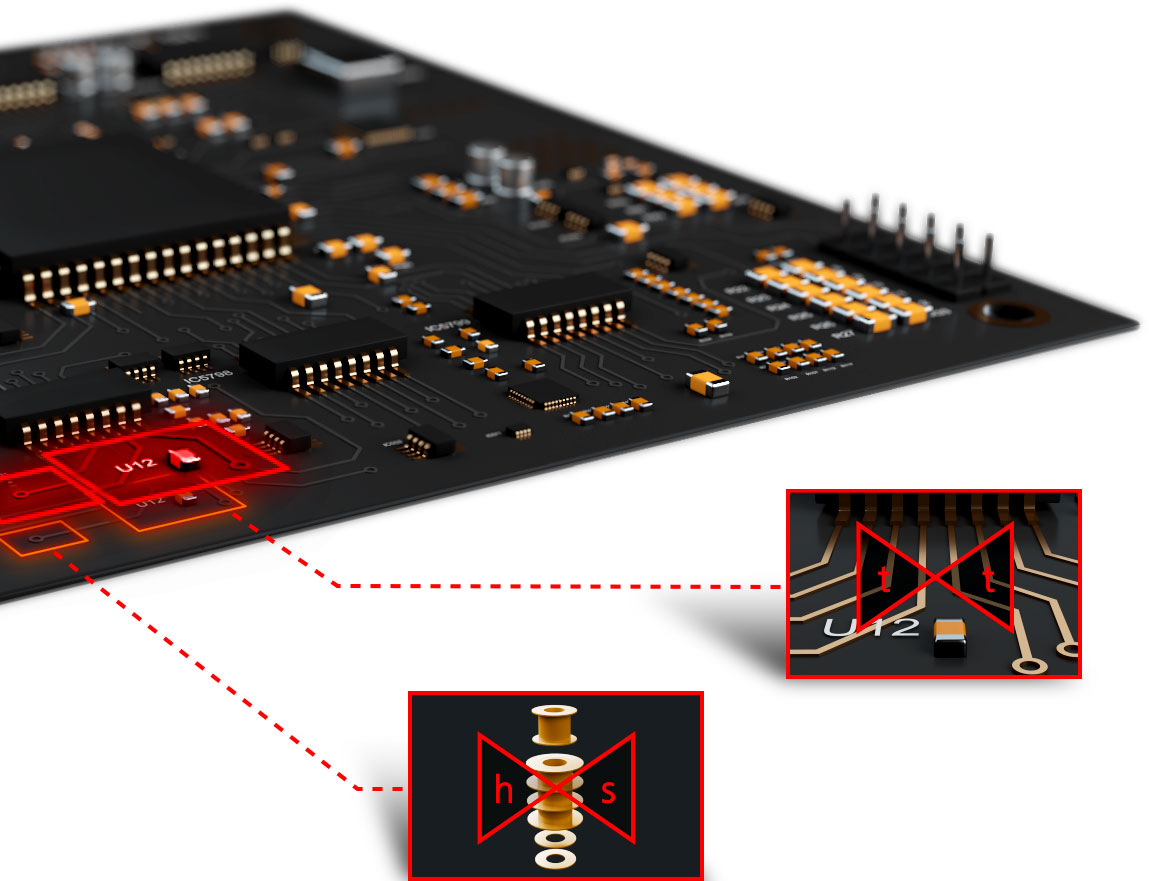
OrCAD X centralizes DFM constraints and left shifts DFM analysis directly into the PCB layout environment. As you place components and route your board, any manufacturing violations made appear on your canvas based on the constraints set, allowing you to resolve issues in real-time.

Key Benefits of Streamlined Manufacturing
Better Cost Reduction - Minimize production costs by reducing material waste, assembly time, and rework
Improved Quality - Prevent a range of issues or defects during production by optimizing product design and improving the manufacturing process
Enhanced Reliability - Optimize the shape, dimensions, and materials to improve its durability and reliability
Shorten Time to Market - Uncovering issues means rework and redesign, which wastes time, resources, and extends the product development cycle
Improve Production Efficiency - Avoid common manufacturing errors based on manufacturing process requirements and limitations
Key Features

Sharing and Collaboration
Easily work with contract manufacturers, design houses and consultants using shared workspaces through OrCAD X OnCloud.

Seamless Management
Version control all release content to ensure the right design version is matched to the output and documentation.

In-Design DFM
Rely on the robust set of real-time DFM checks within your PCB layout environment to ensure your designs are manufactured reliably and cost-effectively.

BOM Optimization
Validate and improve part cost, lead time, and alternate sourcing from a centralized dashboard.
Design for Fabrication
When you submit your designs for fabrication, you want success on the first pass. OrCAD X PCB Editor enables that with real-time fabrication, assembly, and test checks.
NEXT STEPS
Ready to get started with OrCAD X?
© 2025 Cadence Design Systems, Inc. All Rights Reserved.


